


All
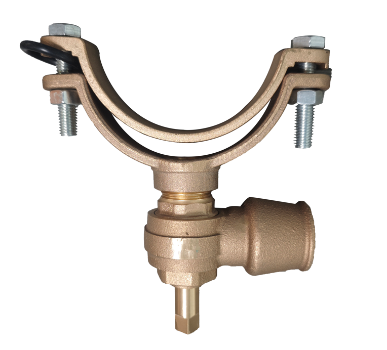
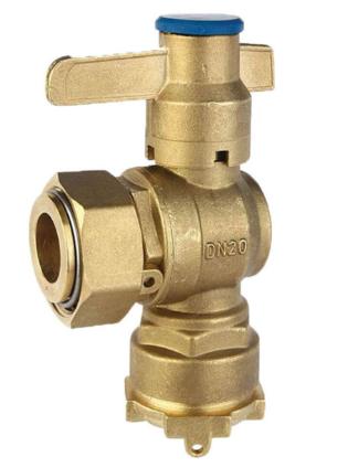
Brass sleeve valve
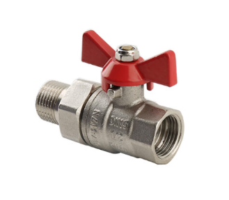
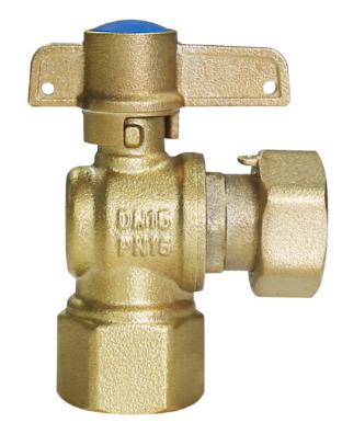
Brass Straight Ball Valve With Union
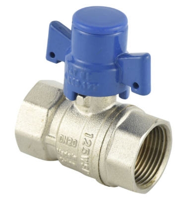
Brass Lock Valve With Nickel Plated For Saudi Arabic Market
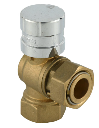
L06 Female Thread Brass Magnetic Angle Type Lockble Valve
L05 Long Design Mechanical Handle Both Female Threaded Lockable Valve
L02 CW617N Brass Material Angle Type Anti Fraud Ball Valve
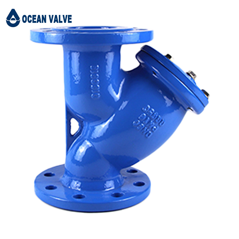
Y-type Strainer
Y type Strainer is the filtration equipment which is to prevent impurities in the flow media from flowing into the back-end equipment. The strainer is usually being installed before the Water.
Features:
- Face to face: DIN3202-F1 / BS 2080
- Flanges: BS4504 / EN 1092-2 PN10/16
- Pressure Rate: PN10/16
- Hydraulic pressure test to EN12266 1.5 x PN
- Coating: Fusion bonded epoxy coating
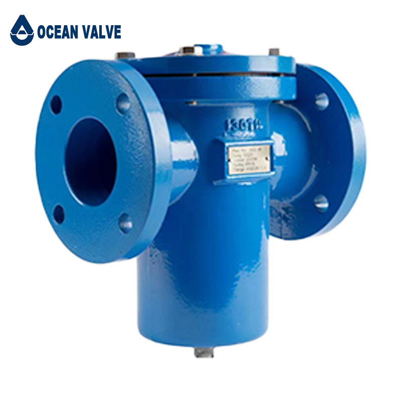
Basket Filter
It is mainly composed of connection pipes, main pipes, filter baskets, flanges, flange covers and fasteners. When the liquid enters the filter basket through the main pipe, the solid impurity particles are blocked in the filter basket, and the clean fluid passes through the filter basket and is discharged from the filter outlet. When cleaning is required, unscrew the screw plug at the bottom of the main pipe, drain the fluid, remove the flange cover, and reinstall it after cleaning. Therefore, it is extremely convenient to use and maintain.
Foot Valve
Description
The foot valve is a kind of check valve. It is a valve used to prevent the medium in the pipeline from flowing back. The foot valve is opened when the medium flows downstream, and the foot valve is automatically closed when the medium flows backward. The foot valve is equipped with multiple water inlets on the bonnet, and is equipped with a screen to reduce the inflow of debris, which are not easy to be blocked.
Standards
▪ Size range: DN50 - DN300
▪ Connection Ends: EN 1092-2, PN10/16
▪ Nominal Pressure: PN10/16
▪ Temperature Range: 0℃ - 80℃
▪ Coating: Fusion bonded epoxy powder coating with min 250 microns thickness inside and outside

Pressure Differential Valve
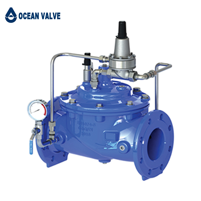
Pressure Relief Valve
Hydraulically operated, pilot-controlled, pressure relief valve designed to maintain constant upstream pressure within close limits. This valve can be used for pressure relief, pressure sustaining, back pressure functions in a by-pass system. In operation, the valve is actuated by line pressure through a pilot control system, opening fast to maintain steady line pressure but closing gradually to prevent surges. Operation is completely automatic and pressure settings may be easily changed by adjusting screw on top of the pilot.
Operation
▪ Open all isolation valves in pilot system.
▪ Remove pilot cap and loose the jam nut of pilot.
▪ Observe the setting on the Pressure relief valve pilot . Normally the factory outgoing sets outlet pressure as 4 bar. If 4 bar is higher than needed, turn the adjusting screw anti-clockwise. Pressure change about 0.5bar one turn until close to the required pressure. This setting is approximate and may have to be changed once the valve is pressurized.
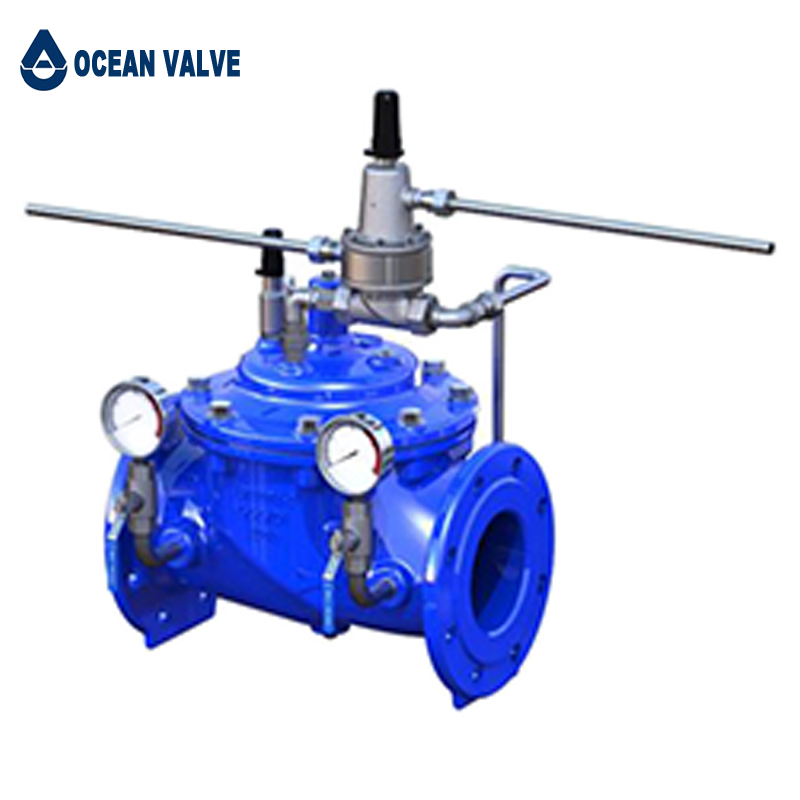
Pressure Reducing Valve
Our pressure reducing valve is a hydraulically driven, pilot valve-controlled control valve. Automatically reduces a higher inlet pressure to a steady lower downstream pressure, regardless of changing flow rate and/or varying inlet pressure.
This valve is an accurate, pilot-operated regulator capable of holding downstream pressure to a pre-determined limit. No matter how the flow rate or pressure before the valve fluctuates and changes, the valve can reduce the pre-valve high pressure to the post-valve low pressure and keep it stable, even if the valve does not have user water. It can keep the outlet pressure stable.


